5t4nd1ng @ th3 3dg3 0f 5p3ct4t10n!
Welcome to Walt Perko's Brainless.org-anizm
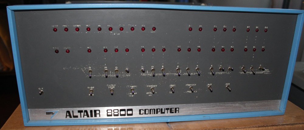
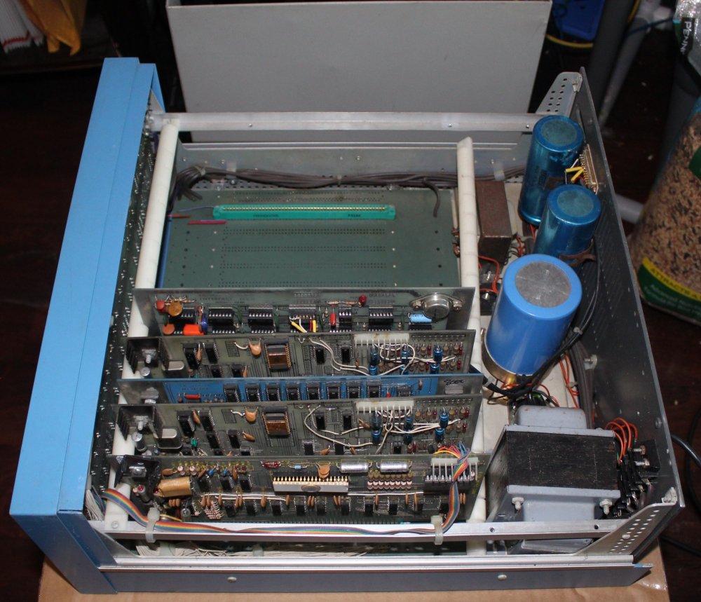
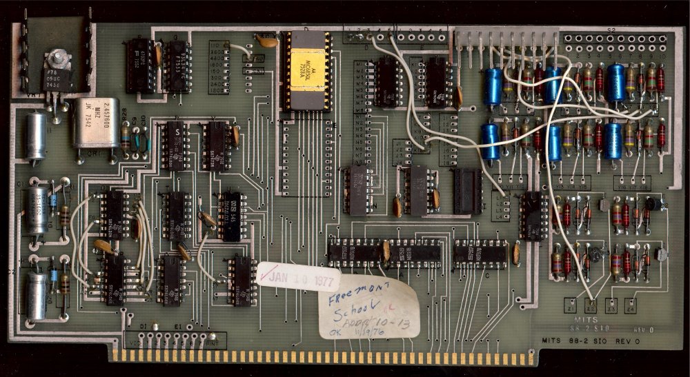
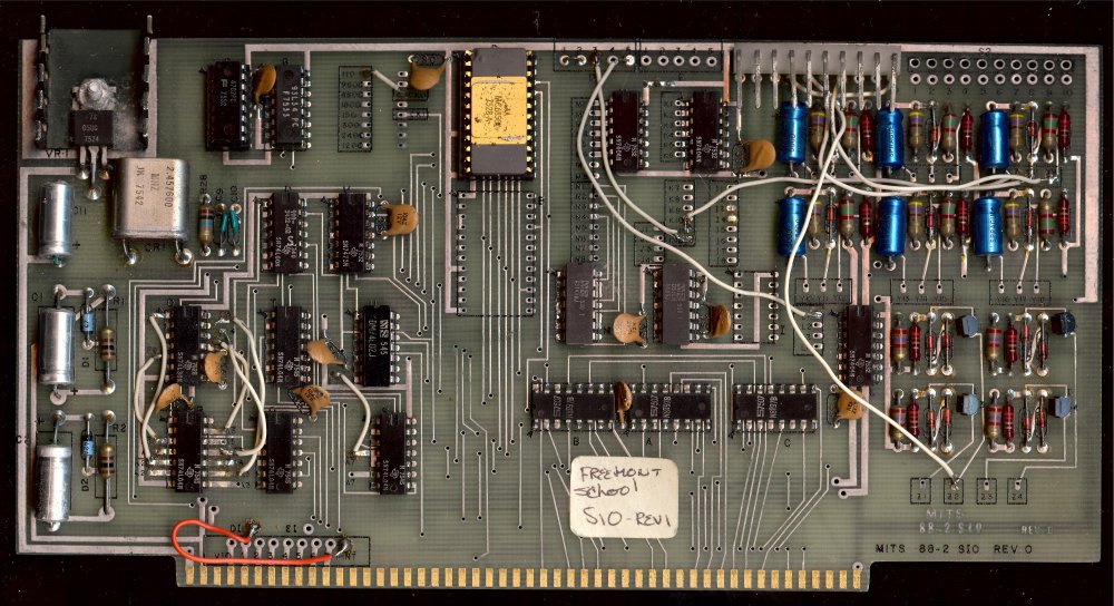
After exploring inside of my new computer and imaging the S-100 circuit boards and other guts, I found this computer once belonged to Fremont School. Now I'm working on tracking it's original provenance. . |
. |
|
. |
In the meantime, after testing the power supply to be usable, I was able to add a longer bolt to allow DB25 connectors in the back panel. |
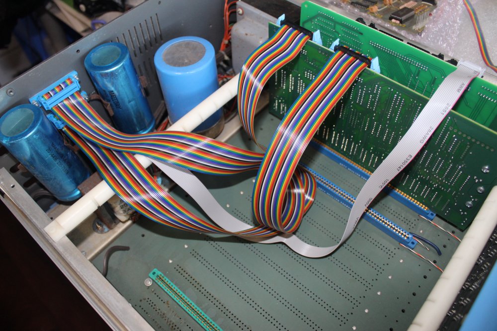
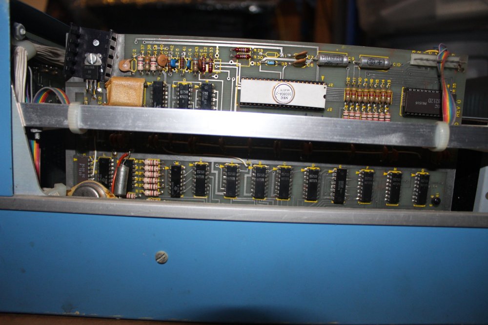
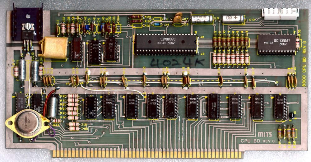
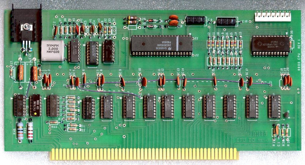
A closer look at the boards
|
|
. |
|
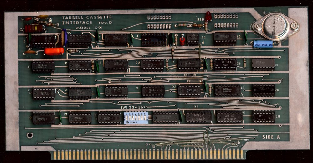
This board is For Sale or Trade . |
This board is For Sale or Trade |
|
|
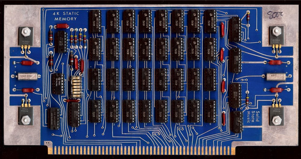
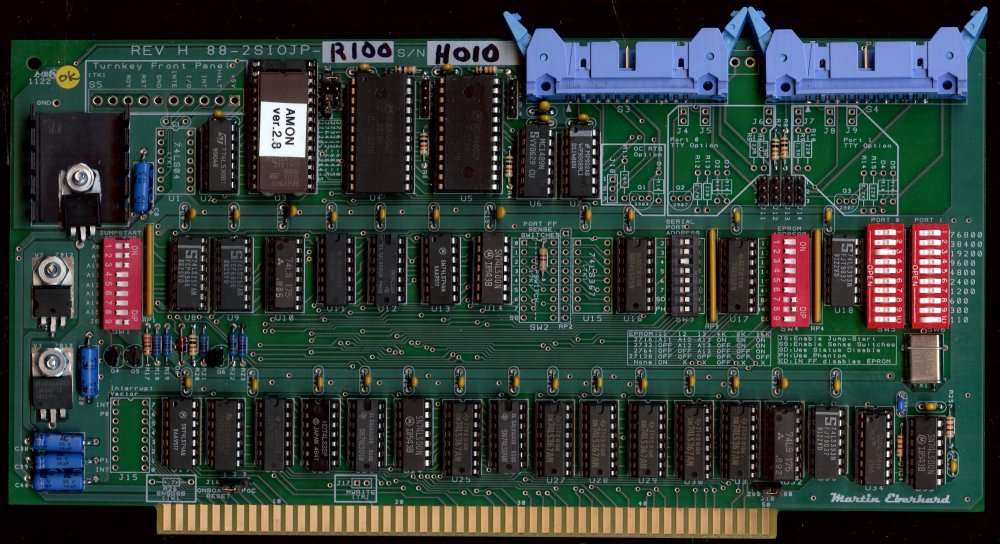
The best solution for 64K RAM and PC Serial Drive Server serving four Floppy Drives to the computer! . |
Smarter and easier to use/configure 88-2SIO design
|
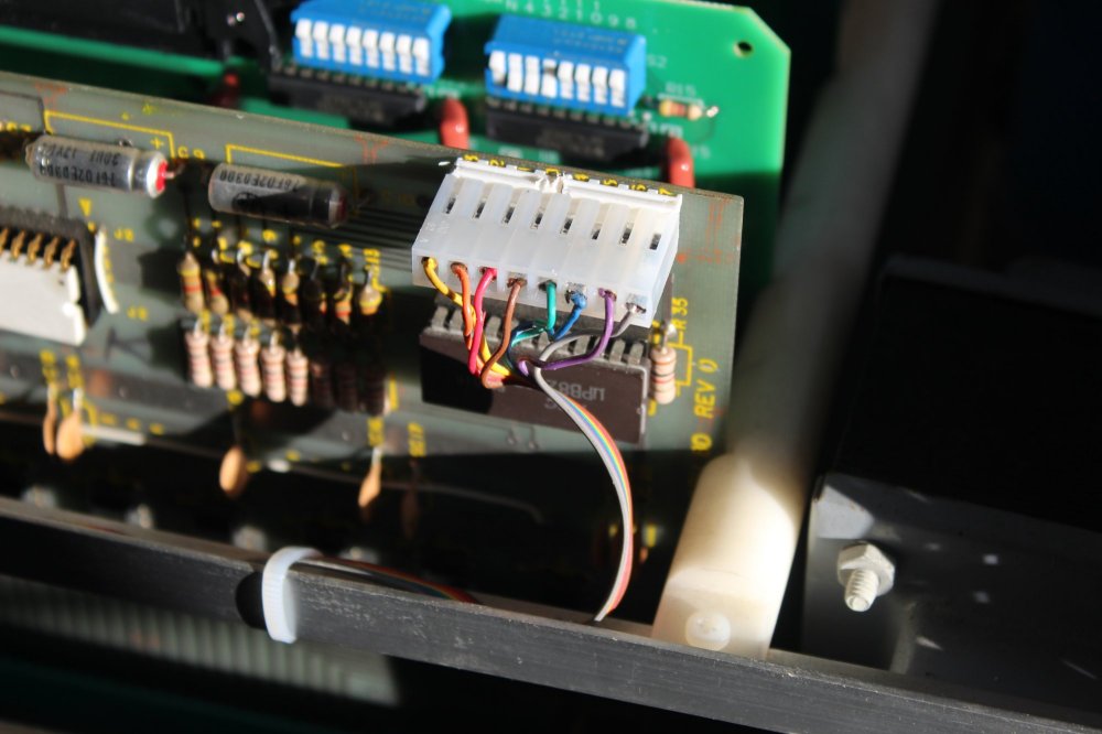
Wires soldered to the back of the board After Front Panel Cable Repairs
. |
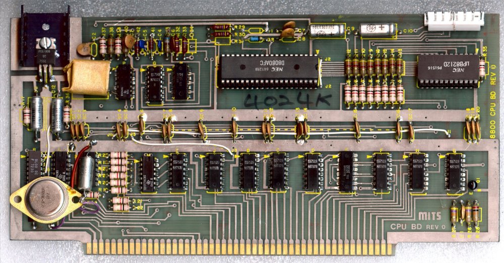
LM320K-5.0 Voltage Regulator in lower left corner
|
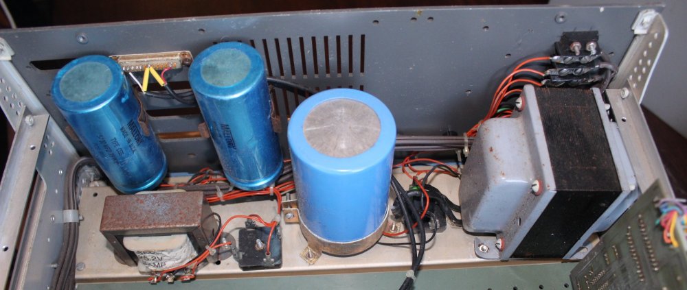
Per the manual checking power supply voltages on the buss without any boards in any slots
Testing with an oscilloscope the ripple or 60Hz hum on the d.c. voltages I cannot see any ripple, this is a sign of good capacitors Next test was a continuity test between the solder points on the front of the front panel to the solder points on the back of the CPU board to insure the connections are all good. |
as of Earth Date: 20230704
|
Why is there a second 5V regulator kluged on the board? Are both in parallel or is the one on the top disconnected? |
It takes about $100 and a couple of hours to assemble
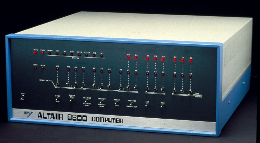
Next step, test the new CPU board in my Altair 8800c computer
.
|
?????????????? . |
??????????????
|
?????????????? . |
??????????????
|
|
; TEST PROGRAM TO CONTINUALLY SEND A TO Z CHARACTERS TO THE SERIAL PORT AT 10H,11H |